เข้าชม : 6980 | สั่งซื้อไปแล้ว : 0 | Wishlist Rate : 0
เพิ่มลง Wishlist
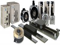
Servo Yaskawa Sigma II
Servo Yaskawa Sigma II Amplifier is the ultimate servo solution for your automation needs. A single platform covers 30 watts to 55 kW and input voltages of 110, 230 and 480 VAC. The Sigma II amplifier can be set to torque, speed, or position control. A single-axis controller and a variety of network interface modules can be attached to the amplifier for the utmost flexibility. The Sigma II amplifier utilizes serial encoder technology to automatically recognize Sigma II rotary and linear servomotors. Advanced algorithms provide high performance tuning and suppression of machine resonance. A built-in keypad and serial port allow easy set-up and monitoring of the servo system. SigmaWin and SigmaWin Plus software can be used to capture torque, speed, and command references and SigmaWin Plus Professional can perform FFT and machine simulations.

Design Features for SGDH Sigma II
|
Improved Performance
-
Higher bandwidth response (400Hz speed loop frequency response)
-
Positioning settling time shortened to 1/2 to 1/3
-
Smooth control at low rpm made possible by Sigma II servomotors’ high resolution feedback
Easy Operation
-
All-in-one model (speed, torque, and position control)
-
PC monitoring function available including graphical tuning and file storage
-
Adaptive-tuning function
-
Multi-axis communication provided as standard
-
One PC can communicate with up to 14 SGDH units by parameter setting
-
Built-in parameter setting device
-
On-board storage of alarm history
-
Automatic determination of motor settings at connection
Additional Functionality with Ready-to-Install Application Modules
-
Configurable single-axis controls including serial networking capability
-
Fieldbus connectivity (Devicenet, Profibus, etc.)
-
Full closed loop (optional position feedback)
-
Yaskawa MP940 single-axis motion controller
Certified International Standards
-
UL, cUL listed (File #: E147823), CE compliance
|
Model Number Designation for SGDH Sigma II


Specifications for SGDH Sigma II
100V/200V
|
Basic Specifications |
Input Power Supply |
Main Circuit1 |
Three-phase (or single-phase) 200 to 230VAC +10% to -15%, 50/60 Hz, or single-phase 100 to 115VAC +10% to -15%, 50/60 Hz |
|
Control Circuit1 |
Single-phase 200 to 230VAC (or 100 to 115VAC) +10% to -15%, 50/60 Hz |
|
Control Mode |
Three-phase, full-wave rectification IGBT PWM (sinusoidal commutation) |
|
Feedback |
Serial incremental encoder, absolute encoder |
|
Location |
Ambient/Storage Temperature2 |
0 to 55ºC / -20 to 85ºC |
|
Ambient/Storage Humidity |
90% or less (no-condensing) |
|
Vibration/Shock Resistance |
4.9m/s2/19.6m/s2 |
|
Structure |
Base mounted (duct ventilation available as option) and flat mount type |
|
Speed/Torque Control Mode |
Performance |
Speed Control Range |
1 : 5000 (The lowest speed of the speed control range is the speed at which the servomotor will not stop with a rated torque load.) |
|
Speed Regulation3 |
Load Regulation |
0% to 100%: 0.01% max. (at rated speed) |
|
Voltage Regulation |
Rated voltage ±10% : 0% (at rated speed) |
|
Temperature Regulation |
25 ± 25º°±C : 0.1% maximum (at rated speed) |
|
Frequency Characteristics |
400Hz (at JL = JM) |
|
Accel/Decel Time Setting |
0 to 10s (Can be set individually for acceleration and deceleration). |
|
Input Signal |
Speed Reference |
Reference Voltage4 |
±6VDC (variable setting range: ±2 to ±10VDC) at rated speed (forward rotation with positive reference); input voltage: ±12V (maximum) |
|
Input Impedance |
Approximately 14kW |
|
Circuit Time Constant |
— |
|
Torque Reference |
Reference Voltage4 |
±3VDC (Variable setting range: ±1 to ±10V) at rated torque (forward rotation with positive reference), input voltage: ±12VDC (maximum) |
|
Input Impedance |
Approximately 14kW |
|
Circuit Time Constant |
Approximately 47µs |
|
Contact Speed Reference |
Rotation Direction Selection |
Uses P control signal |
|
Speed Selection |
Forward/reverse rotation current limit signals are used (1st to 3rd speed selection). When both signals are OFF, the motor stops or enters another control mode. |
|
Positioning Control Mode |
Performance |
Bias Setting |
0 to 450rpm (setting resolution: 1rpm) |
|
Feed-forward Compensation |
0 to 100% (setting resolution: 1%) |
|
Position Complete Width Setting |
0 to 250 reference units (setting resolution: 1 reference unit) |
|
Input Signal |
Reference Signal |
Type |
Sign + pulse train, 90º phase difference 2-phase pulse (phase A + phase B), or CCW + CW pulse train |
|
Pulse Buffer |
Line driver (+5V level), open collector (+5V or +12V level) |
|
Pulse Frequency |
Maximum 500/200kpps (line driver/open collector) |
|
Control SIgnal |
CLEAR (input pulse form identical to reference pulse) |
|
Built-in Open Collector Power Supply 5 |
+12V (With built-in 1kW resistor) |
|
I/O Signals |
Position Output |
Output Form |
Phases A, B and C: Line driver output
Phase S: Line driver output (Only when absolute encoder is used) |
|
Frequency Dividing Ratio |
Any |
|
Sequence Input |
Servo ON, P control (or forward/reverse rotation in contact input speed control mode), forward rotation prohibited (P-OT), reverse rotation prohibited (N-OT), alarm reset, forward rotation current limit, and reverse rotation current limit (or contact input speed control) |
|
Sequence Output |
— |
Servo alarm, 3-bit alarm codes |
|
Configurable: (Any 3 of these signals) |
Positioning complete (speed coincidence), servomotor rotating, servo ready, current limit, brake release, warning, and near position signals |
|
Built-in Functions |
Dynamic Brake (DB) |
Activated at main power OFF, servo alarm, servo OFF or overtravel |
|
Regenerative Processing |
Incorporated. For 60 to 1A types, external regenerative resistor must be mounted. |
|
Overtravel (OT) Prevention |
Motor decelerates or coasts to a stop, or is stopped by a dynamic brake. |
|
Protection |
Overcurrent, overload, regenerative error, main circuit voltage error, heat sink overheat, power open phase, overflow, overspeed, encoder error, encoder disconnected, overrun, CPU error, parameter error. |
|
LED Display |
POWER, CHARGE, five 7-segment LEDs (built-in digital operator functions) |
|
Analog Monitor (5CN) |
Built-in analog monitor connector to observe speed, torque, and other reference signals
Speed: 1V/1000rpm
Torque: 1V/rated torque
Pulses remaining: 0.05V/reference units or 0.05V/100 reference units |
|
Communication |
Interface |
Digital operator (mount type or hand-held)
RS-422A port such as person computer (RS-232C port can be used if some conditions are met). |
|
1 : N Communication |
N can be up to 14 when RS-422A port is used. |
|
Axis Address Setting |
Set via user parameters |
|
Functions |
Status display, user constant setting, monitor display, alarm traceback display, jogging, autotuning, speed/torque reference signals, other graphing functions, etc. |
|
Others |
Reverse rotation connection, home position search, automatic servomotor ID, DC reactor connection terminal for high power supply frequency control. |
1 The power voltage must not exceed 230V +10% (253V). If it is likely that it will exceed this limit, use a step-down transformer. For types SGDH-08AE-S and SGDH-15AE-S, voltage is 200 to 230V + 10% -5%.
2 Use the servo amplifier within the ambient temperature range. When enclosed, the temperatures inside the cabinet must not exceed the specified range.
3 Speed regulation is defined as follows:
Speed Regulation = (no-load motor speed - full load motor speed) / rated motor speed x 100%
4 Forward is clockwise viewed from the non-load side of the servomotor, (counterclockwise viewed from the load and shaft end).
5 The built-in open collector power supply is not electrically isolated from the control circuit in the servo amplifier.
400V
|
Basic Specifications |
Input Power Supply |
Main Circuit |
Three-phase 380 to 480VAC +10% to -15%, 50/60 Hz. |
|
Control Circuit |
1. 24VDC ±10% to ±15%, 1A (maximum)
2. 24VDC ±10%, 40W for 22 to 55kW units
Note: For 22 to 55kW units only, the power supply for the optional dynamic brake (DB) contactor is made from the control circuit power supply. If DB operation is necessary when the power interruption occurs, maintain the DC24V while the DB operates. If 5 times inertia is attached and a standard DB resistor is used, DB operation time is approximately 2 to 5 seconds. |
|
Control Mode |
Three-phase, full-wave rectification IGBT PWM (sinusoidal commutation) |
|
Feedback |
Serial incremental encoder, absolute encoder |
|
Location |
Ambient/Storage Temperature1 |
0 to 55ºC / -20 to 85ºC |
|
Ambient/Storage Humidity |
90% or less (non-condensing) |
|
Vibration/Shock Resistance |
1. 4.9m/s2 / 19.6m/s2 for 500W to 15kW units
2. 9.8m/s2 (1G) / 49m/s2 (5G) for 22 to 55kW units
Cyclic shock resistance is 29m/s2 (3G) |
|
Structure |
Base mounted (duct ventilation available as option) and flat mount type |
|
Speed/Torque Control Mode |
Performance |
Speed Control Range |
1 : 5000 (The lowest speed of the speed control range is the speed at which the servomotor will not stop with a rated torque load.) |
|
Speed Regulation2 |
Load Regulation |
0% to 100%: 0.01% max. (at rated speed) |
|
Voltage Regulation |
Rated voltage ±10% : 0% (at rated speed) |
|
Temperature Regulation |
25 ± 25ºC : 0.1% maximum (at rated speed) |
|
Frequency Characteristics |
400Hz (at JL = JM)
Note: 100 Hz (JL = JM) for 22 to 55kW systems |
|
Accel/Decel Time Setting |
0 to 10s (Can be set individually for acceleration and deceleration). |
|
Input Signal |
Speed Reference |
Reference Voltage3 |
±6VDC (variable setting range: ±2 to ±10VDC) at rated speed (forward rotation with positive reference); input voltage: ±12V (maximum) |
|
Input Impedance |
Approximately 14kW |
|
Circuit Time Constant |
— |
|
Torque Reference |
Reference Voltage3 |
±3VDC (Variable setting range: ±1 to ±10V) at rated torque (forward rotation with positive reference), input voltage: ±12VDC (maximum) |
|
Input Impedance |
Approximately 14kW |
|
Circuit Time Constant |
Approximately 47µs |
|
Contact Speed Reference |
Rotation Direction Selection |
Uses P control signal |
|
Speed Selection |
Forward/reverse rotation current limit signals are used (1st to 3rd speed selection). When both signals are OFF, the motor stops or enters another control mode. |
|
Positioning Control Mode |
Performance |
Bias Setting |
0 to 450rpm (setting resolution: 1rpm) |
|
Feed-forward Compensation |
0 to 100% (setting resolution: 1%) |
|
Position Complete Width Setting |
0 to 250 reference units (setting resolution: 1 reference unit) |
|
Input Signal |
Reference Signal |
Type |
Sign + pulse train, 90° phase difference 2-phase pulse (phase A + phase B), or CCW + CW pulse train |
|
Pulse Buffer |
Line driver (+5V level), open collector (+5V or +12V level) |
|
Pulse Frequency |
Maximum 500/200kpps (line driver/open collector) |
|
Control SIgnal |
CLEAR (input pulse form identical to reference pulse) |
|
Built-in Open Collector Power Supply 4 |
+12V (With built-in 1kW resistor) |
|
I/O Signals |
Position Output |
Output Form |
Phases A, B and C: Line driver output
Phase S: Line driver output (Only when absolute encoder is used) |
|
Frequency Dividing Ratio |
Any |
|
Sequence Input |
Servo ON, P control (or forward/reverse rotation in contact input speed control mode), forward rotation prohibited (P-OT), reverse rotation prohibited (N-OT), alarm reset, forward rotation current limit, and reverse rotation current limit (or contact input speed control) |
|
Sequence Output |
— |
Servo alarm, 3-bit alarm codes |
 |
Configurable: (Any 3 of these signals) |
Positioning complete (speed coincidence), servomotor rotating, servo ready, current limit, brake release, warning, and near position signals |
|
Built-in Functions |
Dynamic Brake (DB) |
Activated at main power OFF, servo alarm, servo OFF or overtravel |
|
Regenerative Processing |
Incorporated. For 6 to 55kW units, external regenerative resistor must be mounted. |
|
Overtravel (OT) Prevention |
Motor decelerates or coasts to a stop, or is stopped by a dynamic brake. This requires optional dynamic brakes for 22 to 55kW units. |
|
Protection |
Overcurrent, overload, regenerative error, main circuit voltage error, heat sink overheat, power open phase, overflow, overspeed, encoder error, encoder disconnected, overrun, CPU error, parameter error. |
|
LED Display |
POWER, CHARGE, five 7-segment LEDs (built-in digital operator functions) |
|
Analog Monitor (5CN) |
Built-in analog monitor connector to observe speed, torque, and other reference signals
Speed: 1V/1000rpm
Torque: 1V/rated torque
Pulses remaining: 0.05V/reference units or 0.05V/100 reference units |
|
Communication |
Interface |
Digital operator (mount type or hand-held)
RS-422A port such as person computer (RS-232C port can be used if some conditions are met). |
|
1 : N Communication |
N can be up to 14 when RS-422A port is used. |
|
Axis Address Setting |
Set via user parameters |
|
Functions |
Status display, user constant setting, monitor display, alarm traceback display, jogging, autotuning, speed/torque reference signals, other graphing functions, etc. |
|
Others |
Reverse rotation connection, home position search, automatic servomotor ID, DC reactor connection terminal for high power supply frequency control. |
Models for SGDH Sigma II
|
SGDH-01AE |
SGDH Sigma II Amplifier, Single-Phase, 200V, 100W |
|
SGDH-01BE |
SGDH Sigma II Amplifier, Single-Phase, 100V, 100W |
|
SGDH-02AE |
SGDH Sigma II Amplifier, Single-Phase, 200V, 200W |
|
SGDH-02BE |
SGDH Sigma II Amplifier, Single-Phase, 100V, 200W |
|
SGDH-04AE |
SGDH Sigma II Amplifier, Single-Phase, 200V, 400W |
|
SGDH-05AE |
SGDH Sigma II Amplifier, Three-Phase, 200V, 500W |
|
SGDH-05DE |
SGDH Sigma II Amplifier, Three-Phase, 400V, 500W |
|
SGDH-08AE |
SGDH Sigma II Amplifier, Three-Phase, 200V, 750W |
|
SGDH-08AE-S |
SGDH Sigma II Amplifier, Single-Phase, 200V, 750W |
|
SGDH-10AE |
SGDH Sigma II Amplifier, Three-Phase, 200V, 1kW |
|
SGDH-10DE |
SGDH Sigma II Amplifier, Three-Phase, 400V, 1kW |
|
SGDH-15AE |
SGDH Sigma II Amplifier, Three-Phase, 200V, 1.5kW |
|
SGDH-15AE-S |
SGDH Sigma II Amplifier, Single-Phase, 200V, 1.5kW |
|
SGDH-15DE |
SGDH Sigma II Amplifier, Three-Phase, 400V, 1.5kW |
|
SGDH-1AAE |
SGDH Sigma II Amplifier, Three-Phase, 200V, 11kW |
|
SGDH-1ADE |
SGDH Sigma II Amplifier, Three-Phase, 400V, 11kW |
|
SGDH-1EAE |
SGDH Sigma II Amplifier, Three-Phase, 200V, 15kW |
|
SGDH-1EDE |
SGDH Sigma II Amplifier, Three-Phase, 400V, 15kW |
|
SGDH-20AE |
SGDH Sigma II Amplifier, Three-Phase, 200V, 2.0kW |
|
SGDH-20DE |
SGDH Sigma II Amplifier, Three-Phase, 400V, 2.0kW |
|
SGDH-30AE |
SGDH Sigma II<
|
|

 ทั้งหมด (47)